
RTO — Retentive Timer On
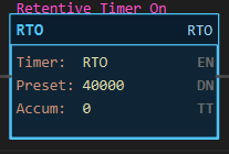
Description
Section titled “Description”RTO (Retentive Timer On) accumulates the total time its rung has been true. Like TON it counts while the rung is true and sets DN when the accumulator reaches the preset. Unlike TON it does not reset when the rung goes false: the accumulator holds its value and continues from there the next time the rung is true. Only a RES instruction clears it. Use RTO to total up run time across interruptions: hours-run on a motor, time-in-cycle for a machine that pauses, a dwell that must add up across several short pushes. Do not use RTO for a plain delay that should start over each time; that is TON, and it needs no RES.
Operands
Section titled “Operands”| Operand | Type | Format | Valid Range | Required | Description |
|---|---|---|---|---|---|
| Timer | TIMER | Tag name or Array[n] |
A TIMER tag owned by no other timer instruction | Yes | The structure that holds this timer’s preset, accumulator and status bits. One RTO per tag. |
| Preset | DINT | Whole milliseconds | 1 to 2,147,483,647 (about 24.8 days) | Yes | Total true time at which DN sets. Stored in the tag as .PRE; editable online. |
| Accum | DINT | Milliseconds | Read-only on the face | — | Total accumulated time, .ACC. Retained while the rung is false. |
The time base is always milliseconds.
Scan Behavior
Section titled “Scan Behavior”Prescan
Section titled “Prescan”EN and TT are cleared. ACC and DN keep whatever they held: a retentive timer’s value is meant to survive.
Rung-condition-in is false
Section titled “Rung-condition-in is false”EN and TT clear. ACC and DN are left exactly as they were. Nothing times.
Rung-condition-in is true
Section titled “Rung-condition-in is true”On the first true scan the timer resumes from the current ACC and EN sets. Each scan ACC is updated with the elapsed time added to what was already accumulated. While ACC is below the preset TT is on and DN is off. When ACC reaches the preset DN sets, TT clears, and ACC stops at the preset.
Postscan
Section titled “Postscan”Nothing special.
Member Bits
Section titled “Member Bits”| Member | Type | Set when | Cleared when |
|---|---|---|---|
.EN |
BOOL | The rung is true | The rung is false |
.TT |
BOOL | The rung is true and ACC is below PRE | ACC reaches PRE, or the rung goes false |
.DN |
BOOL | ACC reaches PRE | RES only |
.PRE |
DINT | The preset, in milliseconds | — |
.ACC |
DINT | Total true time; stops at PRE | RES only |
Example
Section titled “Example”Scenario: A motor may run for a total of forty seconds per batch, in as many starts as the operator likes. After forty seconds a “batch complete” lamp lights until the operator resets.
Tags:
MotorRun— Motor run output, BOOLRTO— TIMER, Preset 40000BatchDone— Batch complete lamp, BOOLAck— Operator acknowledge, BOOL
Rung 1 (the total):
—|XIC MotorRun|———[RTO RTO Preset 40000]———Rung 2 (the lamp):
—|XIC RTO.DN|———(OTE BatchDone)———Rung 3 (the reset):
—|XIC Ack|———(RES RTO)———Start the motor. The rung goes green, EN and TT light, DN stays dark, and the Accum climbs from 0. The screenshot below was taken a little over eight seconds into that first run.
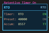
Stop the motor at about nine seconds: the Accum holds there with the rung grey, EN, TT and DN all dark. Run it again for thirty-one seconds: the Accum continues from where it stopped, reaches 40000, DN lights and BatchDone turns on. Stop and start the motor as often as you like now; the Accum stays parked at 40000 and the lamp stays lit.
Press Ack: RES clears the Accum to 0 and DN to 0, the lamp goes out, and the next forty seconds of running start from zero.
See Also
Section titled “See Also”- TON — Timer On Delay (resets when the rung goes false)
- RES — Reset (the only way to clear an RTO)
- TOF — Timer Off Delay
- CTU — Count Up (count RTO cycles for totals beyond one preset)
- Timer and Counter Instructions — Category index
Every RTO needs a RES. Without one the accumulator can only grow and DN, once set, never clears. Put the RES on its own rung, gated by whatever should start the total over.
The accumulator stops at the preset. After DN sets ACC reads exactly PRE however long the rung is true. Choose the preset to be the total you want to detect, not a ceiling; a longer total is a counter counting DN pulses with a RES between them.
Range. PRE and ACC are DINT (32-bit) on every board, so a single RTO can total 24.8 days. For totals beyond that let the RTO’s DN increment a counter and reset the timer on the same scan.
Power cycle. The accumulator lives in the board’s RAM. It survives the rung going false, not a power cycle; the sketch starts with ACC at 0.
Timer arrays. The Timer operand may be an element of a TIMER array. Each element is an independent retentive timer.
Applies to LadderIDE >=1.2.2 · Last reviewed 2026-09-10 · Screenshots verified 2026-09-10