
MSG — Message
Description
Section titled “Description”MSG (Message) reads or writes a block of data between a tag on this controller and a device on the project’s Network tree. One instruction covers every transport LadderIDE speaks: a raw I2C, SPI or UART transfer to a chip, and the industrial protocols DF1, EtherNet/IP, Modbus TCP and Modbus RTU to another controller, drive or meter. On the false-to-true transition of its rung it starts one transfer; the industrial protocols queue the request and complete it over the following scans without blocking the logic. Use MSG whenever data must cross a bus or a network on your command. Do not use MSG for a sensor or output chip that has a catalog entry with member tags; those devices are serviced every scan on their own and need no instruction. Do not hold its rung expecting it to poll; MSG acts once per rising edge.
Operands
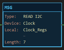
Section titled “Operands”Every field is set in the MSG dialog. The face shows Type, Device, Local and Length.
| Operand | Type | Format | Valid Range | Required | Description |
|---|---|---|---|---|---|
| Direction | Choice | read or write |
— | Yes | Read: remote → Local. Write: Local → remote. |
| Protocol | Choice | i2c spi uart df1 eip modbus-tcp modbus-rtu |
Must match the device | Yes | Picked for you when you choose a device that carries its own protocol (a PLC, a Modbus slave, an Ethernet peer). |
| Port (path) | Comm port | Port name | A port of the board or of an added shield: I2C, SPI, SoftwareSerial, Serial1…, Ethernet |
Yes | Where the device hangs. The device list below it shows only devices on that port. |
| Device (path) | Network device | Device name | A device already added under that port in Explorer ▸ Network | Yes | The target. A device on a different port than the one chosen is a build error. |
| Local data | Tag | Array tag, or an element of one | INT, DINT, REAL or BOOL array; Buf[3] starts the window at element 3 |
Yes | The block on this controller. Its element type decides how the data is marshalled. |
| Length | INT | Literal | 1 to 128, and the window must fit the array | Yes | Number of elements (registers, tag elements or bytes) transferred. |
| Remote address | Varies | See the protocol pages | — | Per protocol | Register (I2C/SPI), start address + area (Modbus), file/element (DF1), tag name (EtherNet/IP). Hidden when the protocol does not use it. |
| Status (opt) | CONTROL tag | Tag name | Any CONTROL tag, one per MSG | No | Carries EN/DN/ER/POS for EtherNet/IP, Modbus TCP and Modbus RTU. Accepted but left at 0 for the raw buses and DF1. |
MSG owns no tag of its own. The Local block and the optional status tag are operands.
Scan Behavior
Section titled “Scan Behavior”Prescan
Section titled “Prescan”Nothing. The edge memory starts false, so a rung already true on the first scan sends one message on that scan.
Rung-condition-in is false
Section titled “Rung-condition-in is false”Nothing new is sent. A queued or in-flight transfer continues to completion. The edge memory is armed.
Rung-condition-in is true
Section titled “Rung-condition-in is true”On the rising edge only:
- Raw I2C / SPI / UART: the transfer happens right there, inside the scan, and the Local block is updated before the next rung runs.
- DF1, EtherNet/IP, Modbus TCP, Modbus RTU: the request is queued. If a status tag is named,
EN= 1 andDN=ER= 0 on this scan. A per-protocol service routine runs the bus a little on every scan until the reply arrives, then writes the Local block (read) and setsDN, or setsERwith the reason inPOS.
Further true scans do nothing until the rung has gone false and true again.
Postscan
Section titled “Postscan”Nothing.
| Protocol | Runs | Blocks the scan | Status tag |
|---|---|---|---|
| I2C, SPI, UART | In the scan, on the edge | For the length of the bus transfer (microseconds to a few ms) | Not filled |
| DF1 | Queued; df1_service() every scan |
No | Not filled |
| EtherNet/IP | Queued; eipc_service() every scan |
No (one bounded 200 ms connect attempt, retried every 2 s) | EN, DN, ER, POS = CIP status |
| Modbus TCP | Queued; mbt_service() every scan |
No (same bounded connect) | EN, DN, ER, POS = exception code |
| Modbus RTU | Queued; mbr_service() every scan |
No | EN, DN, ER, POS = exception code, 255 = no reply |
Status Tag Members
Section titled “Status Tag Members”Optional. Name a CONTROL tag in the Status field; give every MSG its own.
| Member | Data type | Set by | Cleared by | Description |
|---|---|---|---|---|
EN |
BOOL | The rung edge that queues the message | The service routine when the transfer ends | Queued or in flight. |
DN |
BOOL | The service routine on success | The next rung edge | The last transfer succeeded and, for a read, the Local block holds the new data. |
ER |
BOOL | The service routine on failure | The next rung edge | The last transfer failed; look at POS. |
POS |
DINT | The service routine | — | Status code. EtherNet/IP: CIP general status, 0 = OK, 255 = transport failure. Modbus: exception code, 0 = OK, 255 = timeout, CRC, unit or function mismatch. |
LEN, EU, EM, UL, IN, FD |
— | — | — | Not used by MSG. |
Example
Section titled “Example”Scenario: A DS3231 real-time clock on the I2C bus. Its first seven registers hold seconds, minutes, hours, weekday, day, month and year in BCD. A pushbutton reads them into an INT array so the logic can inspect the raw registers. (The clock’s catalog entry also provides decoded member tags every scan; this rung shows the raw path.)
Network tree: Clock — DS3231 RTC on the I2C port, address 0x68.
Tags:
Read_Clock— Read clock registers, BOOLClock_Regs— DS3231 registers 0-6, INT[8]
Rung 1:
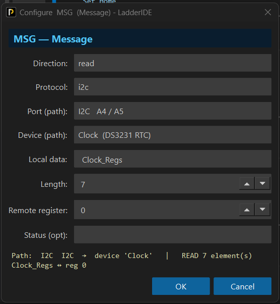
—|XIC Read_Clock|———[MSG READ I2C Device Clock Local Clock_Regs Length 7]———Dialog settings: Direction read, Protocol i2c, Port I2C, Device Clock, Local data Clock_Regs, Length 7, Remote register 0.
Scan 1 — Read_Clock = 0. Nothing is sent. Clock_Regs holds its previous values.

Scan 2 — Read_Clock = 1 (rising edge). On the controller the register pointer is written, seven bytes are read back and land in Clock_Regs[0] to Clock_Regs[6], one byte per element, before the next rung runs.

Values before and after: on hardware Clock_Regs[0..6] go from 0 to the BCD-coded time, for example [37, 18, 9, 4, 11, 9, 38] for 09:18:37 on Thursday 11 September 2038. In the offline simulator MSG does nothing, so the values stay at 0.
See Also
Section titled “See Also”- MSG — I2C, SPI and UART — the raw bus transfers
- MSG — DF1 — Allen-Bradley serial
- MSG — EtherNet/IP — Logix tags by name
- MSG — Modbus TCP — registers and coils over Ethernet
- MSG — Modbus RTU — registers and coils over RS-485 / RS-232
- Adding Network Devices — putting the target on the tree first
- ONS — not needed in front of a MSG
- Communication Instructions — Category index
The device comes first. A MSG can only target a device that is already on the Network tree under the right port. Add the chip, PLC or peer in Explorer ▸ Network, then place the MSG. The path is checked at build time.
One transfer per edge. MSG is self-edge-triggered; an ONS in front of it changes nothing. To poll, drive the rung from a timer’s DN bit and let the timer reset itself, or from a free-running pulse.
Don’t stack edges on a busy queue. A second rising edge while a queued message is still in flight is ignored until the service routine gets to it; on a slow link keep the poll period longer than the reply time. Watch EN if you need to know.
Simulator. MSG does nothing offline: no transfer, no status. Set DN or ER on the status tag in the Tag Browser while simulating to exercise the logic behind it.
Not allowed in an MBS body. A block’s logic may not reach the Network tree.
Sizes. An Uno can carry the raw buses, DF1 and Modbus RTU comfortably. The EtherNet/IP and Modbus TCP clients need frame buffers that leave an Uno’s 2 KB tight; the build warns, and a Mega or STM32 is the comfortable home for them.
Applies to LadderIDE >=1.2.2 · Last reviewed 2026-09-11 · Screenshots verified 2026-09-11