
MSG — Modbus TCP
Description
Section titled “Description”With the protocol set to modbus-tcp, MSG reads or writes a block of registers or bits in a Modbus/TCP server: a VFD, a remote-I/O block, an energy meter, a Siemens or Beckhoff PLC running a Modbus server. The rung’s rising edge queues the request; a client service runs one TCP socket per peer a little on every scan, so the logic never waits. Registers are marshalled to and from INT, DINT and REAL arrays, coils and discrete inputs to and from BOOL arrays. Use it for anything that publishes a Modbus register map. Do not use it as a polling loop held true; it is one request per rung edge.
Operands
Section titled “Operands”| Operand | Type | Format | Valid Range | Required | Description |
|---|---|---|---|---|---|
| Direction | Choice | read / write |
Write is refused on Input Register and Discrete Input areas | Yes | |
| Protocol | Choice | modbus-tcp |
Selected for you when the device is a Modbus TCP peer | Yes | |
| Port | Comm port | Ethernet |
Yes | ||
| Device | Network peer | Name | An Ethernet Device with Protocol = Modbus TCP, IP and TCP port (502) | Yes | Also carries the peer’s 32-bit word order for DINT/REAL. |
| Local data | Tag | INT, SINT, DINT or REAL array for registers; BOOL array for coils / discrete inputs; or Buf[n] |
Window must fit | Yes | INT/SINT = 1 register each, DINT/REAL = 2 registers each, BOOL = 1 bit each. |
| Length | INT | 1 up to one frame (125 registers, 1968 bits) | Build error above the limit | Yes | Elements of Local, not registers: 2 DINTs = 4 registers. |
| Start address | INT | 0 to 65535 | Yes | The first register or bit, 0-based as in the protocol. A vendor’s “40101” is holding register 100. | |
| Modbus area | Choice | Holding Register, Input Register, Coil, Discrete Input | Yes | Which table the start address refers to. | |
| Status (opt) | CONTROL tag | Name | One per MSG | No | EN, DN, ER, POS = exception code (0 = OK, 255 = no reply). |
Scan Behavior
Section titled “Scan Behavior”Prescan
Section titled “Prescan”Nothing.
Rung-condition-in is false
Section titled “Rung-condition-in is false”Nothing new. A queued or in-flight transfer continues. The edge memory is armed.
Rung-condition-in is true
Section titled “Rung-condition-in is true”On the rising edge the request is queued; with a status tag, EN = 1, DN = ER = 0. The client service then connects if needed (one bounded 200 ms attempt, retried every 2 s), sends the function code for the area and direction, and waits up to one second for the reply.
| Area | Read | Write |
|---|---|---|
| Holding Register | FC03 | FC16 (write multiple) |
| Input Register | FC04 | refused at build |
| Coil | FC01 | FC05 (one) / FC15 (several) |
| Discrete Input | FC02 | refused at build |
On success a read is unpacked into Local and DN = 1; a write sets DN = 1. A Modbus exception sets ER = 1 with the exception code in POS; no reply sets ER with POS = 255.
Postscan
Section titled “Postscan”Nothing.
Status Tag Members
Section titled “Status Tag Members”| Member | Data type | Set by | Cleared by | Description |
|---|---|---|---|---|
EN |
BOOL | Rung edge | Service on completion | Queued or in flight. |
DN |
BOOL | Service on success | Next rung edge | Last transfer succeeded. |
ER |
BOOL | Service on failure | Next rung edge | Last transfer failed. |
POS |
DINT | Service | — | Exception code: 1 illegal function, 2 illegal address, 3 illegal value, 4 device failure; 255 = timeout or bad reply. |
Binary Result Display
Section titled “Binary Result Display”Registers are 16 bits, sent big-endian. A DINT or REAL spans two registers; which register carries the high word is the peer’s word-order setting. Drive_Cmd[0] = 1450 written to holding register 100:
Register 100  (INT 1450 = 0x05AA)  bit  15 14 13 12  11 10  9  8   7  6  5  4   3  2  1  0        0  0  0  0   0  1  0  1   1  0  1  0   1  0  1  0  wire  05 AA          (high byte first)
DINT 100000 = 0x000186A0 into registers 200-201  word order ABCD  →  reg 200 = 0x0001   reg 201 = 0x86A0  word order CDAB  →  reg 200 = 0x86A0   reg 201 = 0x0001
Coils pack eight per byte, least-significant bit first: Coils[0] is bit 0 of the first data byte.
Example
Section titled “Example”Scenario: A drive’s Modbus map puts the speed reference in holding register 100 and the run word in 101. Two INT elements are written together on a pushbutton.
Network tree: Eth — W5100 Ethernet Shield on SPI. Drive — Ethernet Device under Ethernet, Protocol Modbus TCP, IP 192.168.1.30, port 502, word order ABCD.
Tags:
Write_Drive— Write drive command, BOOLDrive_Cmd— Speed and run word for the drive, INT[2], preset[1450, 1]Drive_Sts— Drive message status, CONTROL
Rung 1:
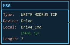
—|XIC Write_Drive|———[MSG WRITE MODBUS-TCP Device Drive Local Drive_Cmd Length 2 Holding 100 Status Drive_Sts]———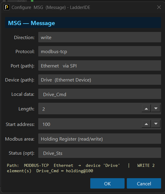
Scan 1 — Write_Drive = 0. Nothing queued. The face lists Drive_Cmd as [1450, 1].
![Figure 2 — Modbus TCP MSG rung false: Write_Drive off, wire dark, the block showing WRITE MODBUS-TCP, Drive, Drive_Cmd [1450, 1], Length 2](/assets/docs/instructions/communication/comm-modbus-tcp-example-rung-1.png)
Scan 2 — Write_Drive = 1 (rising edge). The write is queued, Drive_Sts.EN = 1. On hardware FC16 writes registers 100 and 101 with 1450 and 1, the drive acknowledges, and Drive_Sts.DN = 1.

Values before and after: the drive’s registers 100 and 101 go from whatever they held to 1450 and 1; Drive_Sts.DN 0 → 1. In the simulator nothing is sent.
See Also
Section titled “See Also”- MSG — the instruction and its dialog
- MSG — Modbus RTU — the same areas over a serial line
- MSG — EtherNet/IP — Logix peers
- Adding Network Devices — the shield, the peer and its word order
- Communication Instructions — Category index
Addresses are 0-based. The dialog takes the protocol’s own address. Vendor tables often print “4xxxx” holding-register numbers or 1-based offsets; subtract what the vendor added. The MSG dialog deliberately carries no vendor-specific hints.
Word order is per device. Set it once on the peer to match its manual (ABCD is the Modbus default, CDAB is common on drives and on AutomationDirect CLICK). A DINT that reads as a huge or tiny number is almost always this.
One socket per peer. Every Modbus TCP peer holds a socket for as long as the project runs; count them against the shield’s budget (W5100 four, W5500 eight, the board’s own servers take two).
Length counts elements. Two REALs are four registers; the build checks the register total against the 125-register frame limit and the bit total against 1968.
Memory. About 520 bytes of frame buffer; an Uno builds it with a warning, a Mega or STM32 is comfortable.
Verified against the Modbus TCP server of an AutomationDirect CLICK C2-03CPU over a Mega with a W5500 shield.
Applies to LadderIDE >=1.2.2 · Last reviewed 2026-09-11 · Screenshots verified 2026-09-11