
OTL — Output Latch
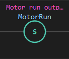
Description
Section titled “Description”OTL (Output Latch) sets a bit to 1 (true) and holds it there until an OTU (Output Unlatch) or RES (Reset) instruction clears it. Use OTL for start/stop logic where a momentary input latches an output on and a separate rung unlatches it. OTL is stateful—the bit persists after the rung goes false on later scans. Do not use OTL for an output that should follow its rung every scan; use OTE for that. Every OTL needs an OTU on another rung, or the bit has no way off short of a reset or power-down.
Operands
Section titled “Operands”| Operand | Type | Format | Valid Range | Required | Description |
|---|---|---|---|---|---|
| Address | BOOL or bit member | Tag name or Tag.bit |
Any writable BOOL tag or INT/DINT bit member | Yes | The tag or bit to latch. When the rung is true, OTL sets this bit to 1 and holds it (the bit does not clear when the rung becomes false). The bit remains latched until OTU or RES clears it. |
Scan Behavior
Section titled “Scan Behavior”Prescan
Section titled “Prescan”OTL initializes the bit to its force value (or 0 if not forced). The latch state persists across rungs.
Rung-condition-in is false
Section titled “Rung-condition-in is false”If the rung conditions are false, OTL does nothing. The bit retains its previous state (latched or not). This is the key difference from OTE: OTE clears the bit, but OTL leaves it alone.
Rung-condition-in is true
Section titled “Rung-condition-in is true”If the rung conditions are true, OTL sets the bit to 1 and holds it latched. On subsequent scans, even if the rung becomes false, the bit remains 1 until OTU or RES clears it.
Postscan
Section titled “Postscan”The latch state is written to the output. The bit persists into the next scan at its latched value.
Example
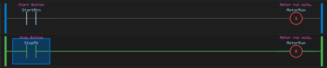
Section titled “Example”Scenario: A start button latches a motor on. A stop button on a separate rung unlatches it. All three tags are memory BOOLs so the example can be stepped in the simulator by toggling the two inputs.
Tags:
StartBtn— Start Button, BOOLStopPb— Stop Button, BOOLMotorRun— Motor run output, BOOL
Rung 1 (Start):
—|XIC StartBtn|———(OTL MotorRun)———Rung 2 (Stop):
—|XIC StopPb|———(OTU MotorRun)———Both coils act on the same bit, so both colour by that bit’s state: orange when it is latched, red while an OTU is actively holding it low, aqua when it is 0 and idle.
Scan 1 — Nothing pressed, motor off:
- Rung 1:
StartBtn= 0, XIC does not conduct, OTL does nothing - Rung 2:
StopPb= 0, XIC does not conduct, OTU does nothing - Result:
MotorRun= 0, both coils aqua (idle)
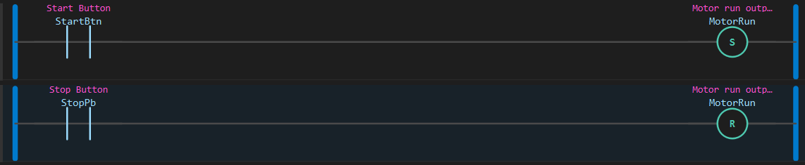
Scan 2 — User presses the start button:
- Rung 1:
StartBtn= 1, XIC conducts (green), OTL setsMotorRun= 1 - Rung 2:
StopPb= 0, OTU does nothing - Result: Motor is latched on; both coils turn orange
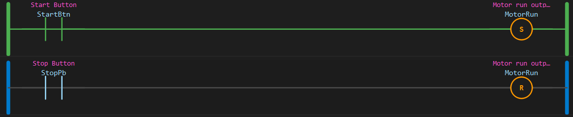
Scan 3 — User releases the start button:
- Rung 1:
StartBtn= 0, XIC does not conduct, OTL does nothing - Rung 2:
StopPb= 0, OTU does nothing - Result: Motor remains on. Neither rung conducts, yet both coils stay orange—the bit is latched
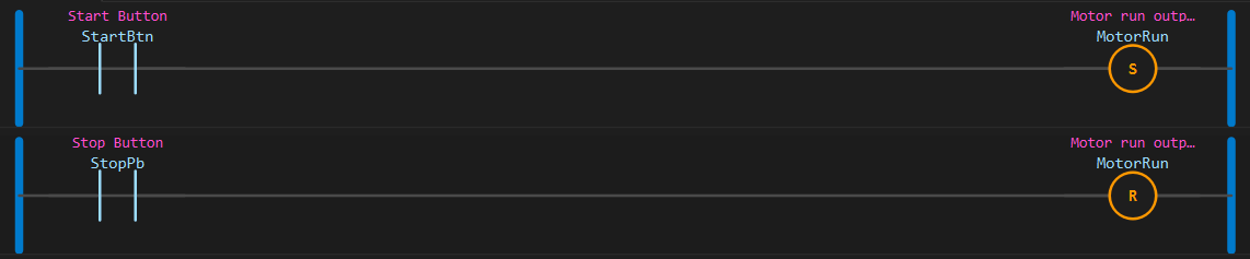
Scan 4 — User presses the stop button:
- Rung 1:
StartBtn= 0, OTL does nothing - Rung 2:
StopPb= 1, XIC conducts (green), OTU clearsMotorRun= 0 - Result: Motor is unlatched and off. Both coils turn red while the stop rung is held true: the OTU is actively holding the bit low. Release the stop button and they return to aqua
See Also
Section titled “See Also”- OTU — Output Unlatch (clears a latched output)
- RES — Reset (also clears latched outputs and data-file state)
- OTE — Output Energize (non-latching, clears when rung is false)
- XIC — Examine If Closed (typical gate for OTL)
- Bit Logic Instructions — Category index
Latch semantics: OTL is idempotent—setting an already-latched bit to 1 is a no-op. The bit persists across scans independent of the rung condition (unlike OTE, which follows the rung every scan).
Unlatch pair: Every OTL should have a corresponding OTU on another rung to release the latch. Without OTU, the bit stays latched until RES or a power-down. For safety-critical applications, always provide an explicit stop path.
Coil colours: OTL and OTU colour by the bit they share, not by their own rung, so the pair always matches. Orange = the bit is set. Aqua = the bit is 0 and nothing is acting on it. Red = the bit is 0 because an OTU on it is gated true right now. A red OTL on a rung whose wire is green means an unlatch rung somewhere is winning every scan—find the OTU that is stuck true.
Last one wins: If an OTL and an OTU on the same bit are both true in one scan, the one later in the scan order sets the final value. In the example the stop rung comes second, so holding both buttons leaves the motor off.
RES interaction: An RES instruction on the same bit address as OTL will clear the latch (and clear the data-file state if the bit belongs to a timer/counter/control structure). See RES documentation for details.
Bit members: OTL accepts INT and DINT bit members—for example, Flags.3 latches bit 3 of the tag Flags. Both the bit and the base word are updated.
Applies to LadderIDE >=1.2.2 · Last reviewed 2026-09-09 · Screenshots verified 2026-09-09